
Product Categories
PRODUCT CATEGORYContact Us
CONTACT USMobile phone:+86-15395152932
mail:[email protected]
Address:Electronic Information Industrial Park, Shunyi District, Beijing City
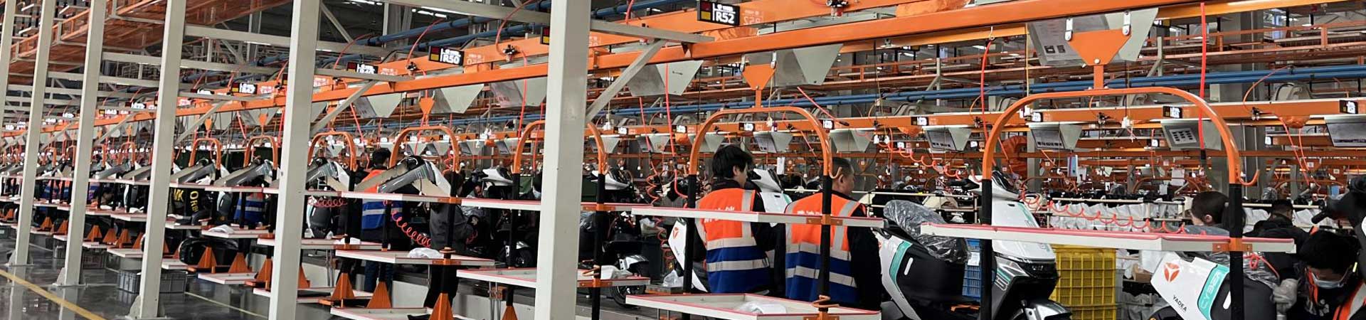
Electric Motorcycle Assembly Line:Heavy-Duty Plate Chain, 40-80N·m Torque & EOL Dynamometer
1. Who this line is for
An electric motorcycle assembly line or e-moped production line is not the same as a lightweight e-bike line. Electric mopeds and electric motorcycles use heavier welded frames, larger hub or mid motors, higher battery voltage, hydraulic disc brakes or large drum brakes, and more safety-critical fasteners. The final assembly system must carry the whole bike plus fixtures, hold positional accuracy for steering geometry, and record torque data for audit.
Typical products covered by this page:
- Electric moped / light e-moped for 25–50 km/h class models
- Electric motorcycle with hub motor or mid-drive, 50 km/h and above
- Cargo-oriented heavy two-wheelers with reinforced rear swingarm
- Mixed e-moped + electric motorcycle line with quick-change fixtures
Long-tail variants naturally used: electric moped assembly line, e-moped production line, electric motorcycle manufacturing line, heavy-duty e-bike assembly machine, electric two-wheeler torque line, 2-wheeler hydraulic brake assembly line.
2. Standard line configuration
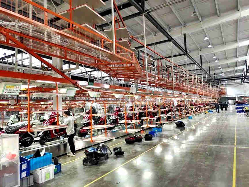
The baseline final-assembly system uses a floor plate-chain main line. Overhead suspension is optional; for heavy frames it is recommended, for refurbished workshops it can be replaced by jib crane + ground material trolley.
Main plate chain
- Total length: 30 m standard, 60–80 m for high-mix or high-takt lines
- Line width: 710 mm including double-side material troughs; wide-body electric motorcycle 800–1000 mm
- Work height: 500 mm ±10 mm, center-stand or dual-stand fixture support
- Chain plate: cold-rolled steel 500×200×2 mm standard, fixture plate 3 mm
- Chain type: special bent-plate needle-roller chain, pitch P=100 mm; light-duty sections can use 50.8 mm, heavy-duty sections enlarged by calculation
- Speed: 0.6–6 m/min variable frequency, continuous / fixed-takt / accumulation modes
- Drive: 2.2 kW gear-reduction motor + inverter for 30 m class; 3 kW dual drive or larger when full loaded length, total vehicle weight and fixture weight require it
- Tension: tail automatic or manual screw/weight tensioner
- Load check: calculate full-line loaded weight = empty chain + fixtures + maximum vehicle weight + suspended parts; verify chain breaking load, support-rail deflection and motor torque rather than quoting one fixed “tonnage”
Overhead suspension auxiliary line
- Truss: carbon-steel square tube or section steel, orange-painted if required
- Load formula: design load = (spreader/fixture tare + frame or plastic-kit max weight) × dynamic factor 1.2–1.5
- Carriers: frame hangers, wheel/motor baskets, large panel trolleys
- Interface: suspension speed linked to plate-chain takt so frames arrive before the fixture reaches the loading station
Utilities per station
- Pneumatic main along light truss, quick coupling every 1.0–1.4 m, spiral PU hose to torque tools
- 220 V socket per station, 380 V reserved at press, brake bleed, test and heavy-lifting stations
- Lighting 300–500 lx on assembly surface, 40 W-class fixture per station or LED equivalent
- SOP board above each station, optional MES terminal showing torque window, BOM, rework history
- Emergency stop every 6–8 m, suspension/plate-chain interlock, pneumatic tool pressure-loss lock
3. Process layout for e-moped / electric motorcycle
The example below assumes a 30 m line, 13 paired stations, 90–120 s takt. Heavy models with more safety points can be extended to 18–26 stations.
A. Frame receiving and numbering
Welded, painted frame from upstream; suspension hanger or crane places it on plate-chain fixture. Check VIN tag, laser or pneumatic marking if not pre-marked. Inspect head-tube weld, swingarm pivot bores, surface coating, grounding points. Fixture locates along longitudinal axis ±1 mm; center-stand/swingarm pins simulate final geometry.
B. Head tube, steering and front fork
Servo or hydraulic press installs upper/lower steering cups. Install fork legs, oil seals, dust covers, stem bearings. For inverted or long-travel motorcycle forks, use fork-support fixtures and check leg parallelism. Mount front wheel later or at fork station depending on wheel size. Torque stem/clamp bolts per bolt grade and diameter; do not use one universal value for all models.
C. Rear swingarm, shock absorber, stands
Install swingarm axle, rear shock(s), side stand, center stand if equipped. Safety items such as swingarm pivot, shock mounts, stand pivots and rear-subframe bolts are tightened with calibrated torque guns. Reference light-two-wheeler assembly data list around 18–30 N·m for items such as center stand and handlebar stem, 30 N·m class for front/rear wheel axles, 4–6 N·m for mudguard brackets and 8–10 N·m for brake-shoe hardware; these are only examples and must be replaced by each model’s engineering torque chart. Heavy e-motorcycle axles, linkage bolts and shock top mounts often require higher values and should be proved by bolt-strength calculation, lubricant condition and joint style.
D. Motor and drive
Hub-motor rear wheel can be pre-assembled offline and loaded as a wheel set; mid-motor lines install motor, primary reduction, chain or belt. Check:
- phase and hall/encoder connectors indexed correctly
- chain sprocket runout <0.5 mm, belt tension per pulley marking
- mid-drive mounting bolts torqued and marked
- wheel axle nut torque per model spec, then rotation check for no drag
For 528-class roller chain or similar motorcycle drivetrains, set tension in the manufacturer’s deflection range and re-check after road-test heat cycle.
E. Controller, DC-DC, BMS pre-install
Mount controller, DC-DC converter, alarm, immobilizer, diagnostics port. Use thermal-conductive pad or bracket for controller cooling. Pre-wire BMS communication for lithium packs. Anti-static mat and ion bar are used for lithium-only stations; lead-acid lines can omit them but still require insulated tooling for high-current terminals.
F. Battery compartment
Install under-seat, floorboard or rear battery. Verify gasket, latch travel, lock mechanism, manual disconnect. Perform BMS wake-up, SOC calibration, insulation-resistance test for lithium systems, and charger handshake test at end-of-line. Keep battery storage isolated from grinding/welding zones.
G. Wiring harness and instruments
Route main harness along frame spine; secure with cable ties/clips at planned intervals. For reference, automotive low-voltage practice often uses tie spacing up to 400 mm and high-voltage harness spacing up to 300 mm, while some domestic electric-bicycle assembly documents simply require secure, non-loose routing; on this line use a documented spacing per harness diameter, e.g. general low-voltage trunk ≤300 mm as a conservative shop standard, battery/high-current loops tighter per BMS spec. Maintain bend radius not less than 6× outer diameter for sensitive signal/high-voltage cables, keep ≥10 mm clearance from moving parts, and apply dielectric grease on wet-zone connectors.
Connect controller, motor, instrument, throttle, brake switches, CAN/485 gateway. Flash speed class, regenerative-brake parameters, TPMS or ABS configuration if equipped.
H. Handlebar and controls
Install handlebar, combined switch, throttle, brake levers, mirrors, instrument cluster. Set handlebar angle and torque stem/clamat per model. Example light-assembly reference values: handlebar stem 18–30 N·m, but heavy motorcycle triple-clamp and bar-clamp bolts may be higher and must follow engineering chart. Check throttle free play, brake-lever reach, and switch orientation.
I. Brake system
Mechanical drum: adjust shoe gap, torque shoe axle, check locknut.
Hydraulic disc: mount master cylinder, caliper, routed hose; bleed until no air; torque banjo/union and caliper mounting bolts; store curve in MES. For ABS models, route wheel-speed sensors, avoid magnetic interference, and verify sensor-air-gap after wheel installation. Record pedal/lever free travel and perform roller drag check before road simulation.
J. Plastics, lighting, security
Front fairing, head cover, side panels, rear trunk, license bracket, mirrors. For motorcycle lines with fewer plastic parts, this zone is shorter; for sport/retro models it expands. Install headlight, tail, turn, brake, horn, GPS/immobilizer. Initial power-on: no CAN fault, instrument self-check, beam pattern, turn 1–2 Hz, horn level per local regulation.
K. Torque audit and fluids
Recheck safety fasteners: steering, swingarm, motor mount, wheel axle, brake mounts, battery lock. Hydraulic brake topping, fork air/oil check where applicable. Apply torque mark paint. Sampling or 100% audit depends on customer quality level.
L. End-of-line dynamic test
Off-load to roller dynamometer/drum:
- no-load and loaded current
- speed vs controller command
- brake distance and balance, disc temperature if instrumented
- headlight intensity, brake-light activation, horn
- BMS voltage/temperature, SOC accuracy
- charger handshake and insulation report for lithium
Output test certificate, VIN-based data file, then transfer by overhead chain, RGV or roller to packing/warehouse.
4. Selection examples
- Electric moped only, 90 s takt: 30 m plate chain, 710 mm, P=100, 0.6–6 m/min, 2.2 kW, light overhead or side trolley, 6–10 torque guns, drum/disc mixed, EOL roller for speed/brake/light.
- Electric motorcycle mixed with moped: 60 m, 800–1000 mm wide, 3 kW dual drive, overhead suspension for frames and wheels, servo fork press, hydraulic brake bench, ABS sensor station, MES torque + CAN archive.
- Cargo/heavy two-wheeler: wider fixture, larger chain section or double-chain support, reduced takt speed, extra swingarm/stand torque stations, reinforced roller test.
5. FAQ
What chain pitch should a heavy e-motorcycle line use?
Start with P=100 mm bent-plate needle-roller chain for the main floor line. If loaded fixture weight, acceleration and accumulation frequency are high, the supplier should verify plate thickness, rail support, sprocket teeth and motor torque instead of using pitch alone.
Do all safety bolts need torque guns?
Steering, swingarm, motor mount, wheel axle, brake caliper/master, battery lock and stand pivots should be torque-controlled. Light brackets can use calibrated manual tools if the quality plan allows.
Is overhead suspension necessary?
Not always. It helps when frames are heavy, when plastic kits are bulky, or when floor aisles must stay clear. Old shops can use jib cranes, monorails at loading stations, or ground trolleys.
How long does a line take to build overseas?
A 30 m CKD/SKD plate-chain line with separated utilities can be containerized; installation and commissioning depend on foundation, power, air supply and staffing, normally several weeks after site readiness.